Virtual Reference

Most buildings, particularly those over 30 years old do not have adequate documentation in the form of digital architectural and engineering drawings. We developed an innovative and technologically advanced solution to this old problem. Our dimensionally-accurate 2D CAD files are designed to facilitate the creation of 3-Dimensional Autodesk Revit and Bentley Architecture BIM models. 

We call these BIM TEMPLATES. Two documented facts must be considered:

For older buildings, the preparation of a BIM model must start with a search for existing drawings. Building information is usually stored in basement plan rooms, where it remains disorganized and incomplete. It consists of rolls of blueprints, sepias, Mylars, and stacks of CD-ROMS of previous “As-Built” drawings, specifications and maintenance records, all stored on a per-project basis. It requires a substantial effort just to reach the BIM starting point. There is no  record of the overall facility all in one single place and format.

After extensive research and analysis, and with a clear understanding of the building documentation available, a BIM model requires painstaking efforts to transfer dimensional information from the “As Built” paper to the computer screen.

The problem is compounded when historical changes over years (renovations and additions) are taken into account. The time and cost required to model existing facilities is still the major issue when working with BIM.  Even with the best software, model generation remains labor intensive and cost-prohibitive.

BIM TEMPLATES offer an elegant solution to these two problems.

We prepare historically-assembled CAD files which depict the current physical state of the facility. Each template represents the true layout of the building as it stands today, in one continuous floor plan file. We call this dataset “As Currently Constructed”. Our CAD files are dimensionally accurate and compliant with the written dimensions shown in the original drawings. These include structural foundation and framing, column and footing schedules, general architectural elements, enlarged plan views, building and wall sections, manufacturer layout drawings, large boilers, chillers and other manufacturing equipment.

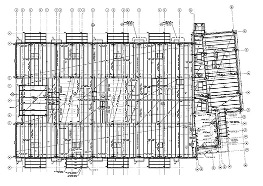
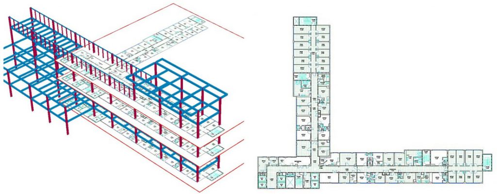
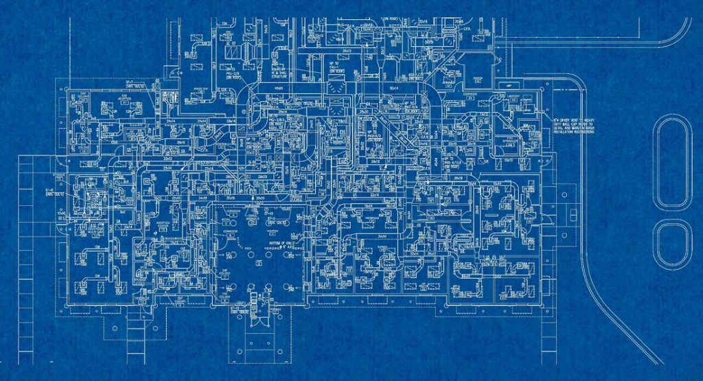
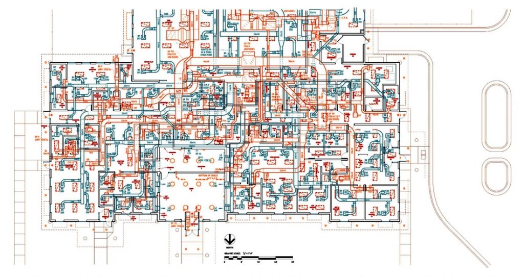
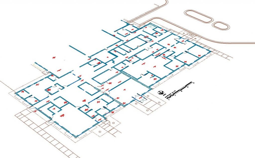
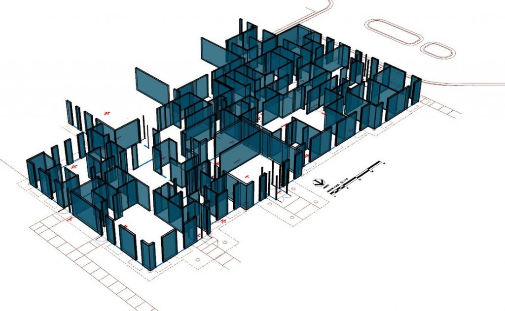
BIM TEMPLATES start with the initial construction set of structural drawings. These documents accurately locate column centerlines, column footprints, and other structural elements such as beams, trusses, girders, slabs and metal decks. To use this information, we have developed software tools to easily convert these old paper drawings into fully accurate structural 3D computer models.

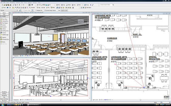
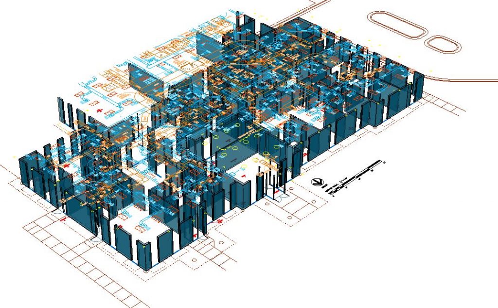
Next, architectural floor plans, as well as other engineering disciplines including mechanical, plumbing, electrical, fire and telecom are converted to 2D vector data and digitally matched to the 3D skeleton of the building. Since each column point becomes a control anchor, overall accuracy is maintained, even for very large and complex structures.

The image below shows the architectural 2D floor plans matched to the structural 3D model. On the right side is the finished and now accurate architectural base floor plan. The same process is repeated for each floor and discipline.
The time sequence component is part of the project as well. Each historic project is sequentially appended to the initial 2D CAD floor plan, essentially constructing the database as the original building was built, one project at a time. Some buildings go through a handful of changes over their life, while others experience hundreds of changes and alterations. Either way, “As Currently Constructed” CAD data truly depicts the current layout of the building.
Every project from initial construction to the present is overlaid, edge-matched and inspected to guarantee linework continuity across contract project limits. This is extremely important, as often the original paper drawings prepared by one AE consulting firm will not include all existing linework information to match with the drawings prepared several years later by a different AE firm. BIM TEMPLATES are carefully checked and matched for continuity. This process is performed for every discipline, from structural and base architectural to mechanical HVAC and piping, electrical power and lighting, plumbing piping and medical or industrial gases, life and fire safety, network and telecommunications.

Once this work is complete, a simple walk-though field verification using a handheld tablet or standard laptop may be conducted to verify the accuracy of the floor plans. Since accuracy is derived from the structural dimensions, only visual confirmation and basic measurements may be need to verify the data. This is much faster than a detailed dimensional survey. It is completed at substantial cost savings. The end-result of this process is our BIM TEMPLATE delivery, either in AutoCAD or MicroStation file formats. Both formats (DWG and DGN) are BIM-ready, and can be readily used as input data to Autodesk Revit and Bentley Architecture BIM models.

By inserting the 2D CAD data into the BIM environment, the creation of accurate 3D model assemblies becomes measurably simpler and quicker. Template-assisted modeling results in substantial time and cost savings. An additional benefit is the consistency between the existing structure and new design models, as the same settings and object “families” can be utilized for both. Also, only essential portions need to be developed into 3D, as some areas of the existing building may remain as 2-D data until future requirements merit additional BIM development.

Below is an example of the typical process of creating a BIM model by using our BIM TEMPLATES. The initial step involves the scanning of existing building documentation, such as the blueprint below. From there, we construct accurate 2D CAD files showing the data contained in the paper originals. Most importantly, CAD files are historically cumulative and geometrically matched to control points established from the structural drawings. All linework is edge-matched across subsequent projects and correctly identified and layered by discipline. Building data are saved using the National CAD Standard to ensure forward compatibility.

After conversion to CAD, floor plans are separated into layers depicting architectural elements, mechanical HVAC and electrical lighting information among others. Annotation and associative dimensions per discipline are kept in individual layers as well. These files can be opened directly in Autodesk Revit and Bentley Architecture, without the need to convert the file format.

Once opened in your BIM software environment, our BIM TEMPLATES appear as shown below, with the engineering discipline layers turned off for clarity.

Using BIM tools and your own families of BIM objects, a model can be developed substantially faster when object points, such as wall corners, door openings, stairs, elevators, ductwork, piping, etc. appear in their dimensionally-accurate position and can be used as “snap” locations without the tedious and time-consuming data entry from original paper drawings. Even in 2D, all data are created at the correct height for the entire building. More over, these files are “As Currently Constructed”, all in one piece and not as isolated renovation project files.

The final image below shows a composite of the architectural model in full registration with the mechanical ductwork layer. Engineering items such as HVAC diffusers, as well as electrical lighting fixtures and fire protection sprinklers appear at the true ceiling height in every floor, all ready for BIM. Your BIM model.
Scroll to Top